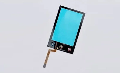
Place the printed circuit into the oven and bake for 40 minutes at a temperature of 115 degrees Celsius. (Note: The circuit with printed lines should dry naturally.) After baking, assemble a simple circuit and test for short circuits, open circuits, excessive resistance, and other issues.
After testing the resistance of the baked circuit, use a laminating machine to apply a layer of insulation tape to the tail wire, starting from the outlet hole and overlapping with the carbon paste by 1 millimeter (try to avoid covering the buttons with the insulation tape).
As a leading custom keypad manufacturer, we suggest the third step is to use a mold to punch out the tail wires, ensuring that both sides of the tail wire are even (pay special attention to tail wires with small line spacing). To create a sample, use a ruler with adhesive, align it with the inner side of the outlet hole, and slide it down to the edge of the tail, making sure the ruler adheres to the back side of the circuit to avoid removing the silver paste.
Place a layer of circuit flat on a properly sized sandwich layer and use a punch to puncture the center point of the circuit key position. Then, use a compass to draw a 10mm diameter circle on the center point (subject to variation in special cases) and tap it down. Use a blade to tap a 2mm wide vent slot between the circular holes of the isolation layer. Make sure there are at least 3 connected circular holes, and avoid crossing the upper and lower circuit intersection points as much as possible. If there are intersection points, seal them with transparent glue. For mass production, use a mold to form the shape in one step.
First, attach the lower circuit with the punched tail wire to the sandwich layer, making sure the silver paste points are placed in the center of the sandwich layer hole without any air bubbles. Then, attach the upper circuit. Make sure the positioning of the upper and lower circuits aligned and the contact points are not offset.
Apply the pre-punched back adhesive to the lower circuit. When applying, the tail wire should be pulled out, and the adhesive should cover the 4 corners. During the entire adhesion process, there should be no air bubbles.
Apply the pre-punched double-sided adhesive to the upper membrane keyboard circuit. Make sure the holes of the double-sided adhesive are aligned with the key positions and cover the 4 corners. (The manufacturing process of the double-sided adhesive is the same as that of the sandwich layer. If there is significant bulge in the panel, the circles can be enlarged, and the adhesive for the spring leaf can be tapped into a 2mm long strip).
Place a scrap panel onto the assembled circuit, align the 4 corners, and enlarge the transparent holes by 1mm to secure them to the assembled circuit. Then, use a suitable blade to punch them out. Be careful not to hit the circuit during punching.
Apply the tested panel to the upper circuit. Align the 4 corners, and if there are air bubbles on the double-sided adhesive, smooth them out. Check if the window is sealed when applying it to the transparent window. After applying, be careful to protect the transparent window.
Cut the tail wires, and for those without terminals, apply a layer of 0.125 single-sided adhesive PET on the back of the carbon paste as reinforcement. For those that require terminals, press the tail wire with the conductive surface facing the terminal with a riveting needle.
Stamping is an indispensable process for membrane switch products, and precise dimensions are required. The design of the mold ensures this. The dimensions should be adjusted based on the dimensions provided by the customer, as well as the thickness, size, and shape of the substrate, in order to produce precise structural dimensions. The quality of the mold is key to the quality of the formed membrane switch. When foaming, the mold should reflect all the patterns on the original version. High-quality foaming should be done with heat pressing, which guarantees that the raised patterns are not deformed and have depth and a three-dimensional effect.