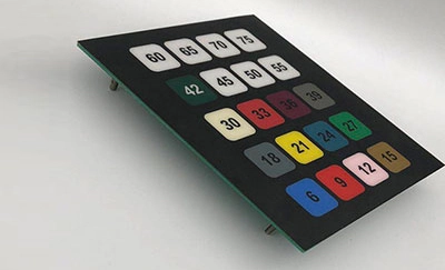
Membrane switch consists of four parts: panel, upper circuit, insulating layer, and lower circuit. It is a light touch-on normally open switch. Under normal circumstances, the two contacts of the membrane switch are in a disconnected state. When an external force is applied to the contacts of the membrane switch, the two normally open contacts are instantly connected. After the external force disappears, the switch contacts return to the normally open state. Usually, the upper circuit contacts bulge or dome pieces are added (good feel). When the membrane switch is pressed, the contacts of the upper circuit are deformed downward and are in contact with the pole plate of the lower circuit. After the finger is released, the contacts of the upper circuit bounce back, the circuit is disconnected, and the circuit triggers a signal. As a professional membrane keypad manufacturer, the Niceone custom membrane keypad has a strict structure, a beautiful appearance, and good sealing performance. It has the characteristics of moisture resistance and long service life. Widely used in electronic communications, electronic measuring instruments, industrial control, medical equipment, the automotive industry, instrumentation, household appliances, military equipment, and other fields.
(1) Material: substrate, silver paste, carbon ink, spacer, adhesive, reinforcing plate, and insulating printing shall comply with the drawings.
(2) Shape: the shape, conductor circuit, insulation treatment, lining board combination, etc. shall comply with the drawings or provide physical samples.
(1) Combination state: There should be no residual material chips, foreign bodies, stains, bumps, or grease attached to the surface and inside, fingerprints on the circuit, and burrs on the punched shape on the surface.
(2) Scratches: All lines and contacts must not have cut marks running through the inside and outside (that is, the cut marks are cut from the line to the substrate). Slight scratches are also based on the principle of not affecting their impedance. The surface of carbon ink is very prone to scratches, and the scratches are based on the principle of not affecting the conduction of the line.
(3) Foreign matter: The line must not have any foreign matter attached to it.
(1) Conductor thickness: Generally, the thickness of the conductor is controlled at 7-12μm, and it should be uniform and smooth.
(2) Defects and pinholes of conductors: according to the drawing standards, one is allowed within each 50mm range.
(3) Carbon ink: The carbon ink covering the silver paste circuit should ensure that the silver paste is completely covered, and its thickness is 8-10 μm, and there should be no obvious protrusion of the silver paste.
(4) Broken and short-circuited: The conductor is not allowed to have any broken or short-circuit phenomenon.
All membrane switch contacts must be free of any insulating ink. The insulating ink surface should be flat to avoid any defects such as air bubbles or pinholes that affect the insulating effect.
(1) Adhesion strength: After the insulating ink is dried, press the ink surfaces against each other for 24 hours to ensure that the insulation does not stick to each other. After sticking with pressure-sensitive tape for 1 minute without air bubbles, peel off quickly, and no ink should fall off.
(2) Jumper: All jumper parts are in accordance with the requirements of line conductors, and all jumper products must undergo 100% open, short-circuit test and insulation resistance tests. Make sure there is no open or short circuit and the insulation resistance should be greater than 500MΩ (500VDC for 1 minute).
(1) Dimensions of punching burrs and die extrusion: The dimensions of punching burrs and extrusion should not be greater than 0.2mm, and the position should be toward the side without conductors.
(2) Position offset of upper and lower lines: The allowable tolerance of the mutual offset of the center positions of the switch contacts of the upper and lower lines is Ф0.5mm.